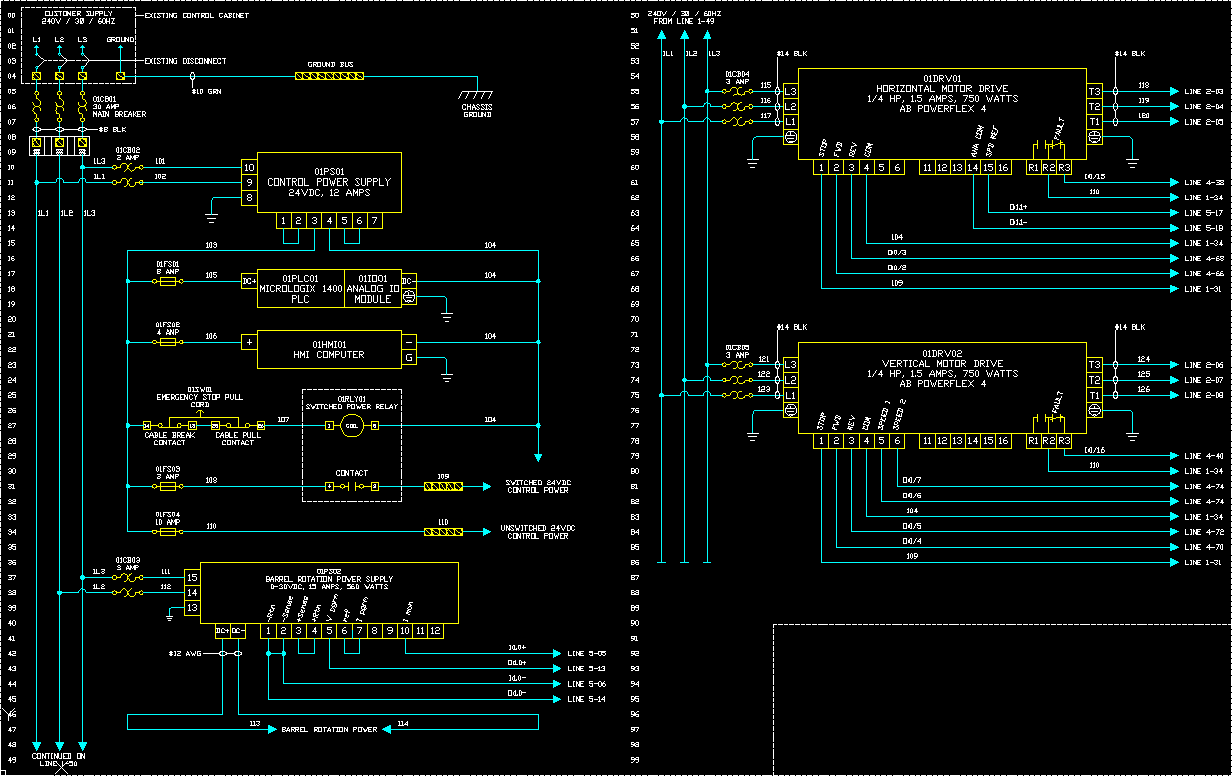


I could also set a max number of contacts to be 8. In the pinlist I could setup a "4,PORT 1,*Port 1 4,PORT 2,*Port 2 etc.". I am looking for a way to create a parent block that has 8 connections (ports) that I can use my RJ45 symbol (child) to carry the port information.Ĭould I treat the Enet switch like a relay and the ports like the contacts. The problem is I don't want multiple parents (8) for one ethernet switch. It would be best if each port were a parent so the RJ45 (child) symbol would carry the port number when it is placed next to the drive. I currently have everything figured out except how to handle the ports in the ethernet switch. This will allow me to see IP information at the ethernet switch for each port as well allow me to surf the parent or sibling blocks. I can then connect the two RJ45 blocks via a cable. I also want to display a RJ45 symbol at the drive that will be a sibling of the ethernet switch and carry port number information. As part of the connection drawing I want to show the IP data (RATING10, 11 &12 ) from the drive at the ethernet switch in the form of a RJ45 symbol. Now that the drive setup is ready I need to show the connection to the ethernet switch. The Hdr2_Enet block then obtains the RATING10, 11 &12 information from the parent. I also have a Hdr2_Enet that is the ethernet module that is plugged into the drive. I then use a Hdr2_XXX to be the control connections for the drive. This block is loaded with RATING10, 11 &12 that represent the ethernet address, subnet and gateway.

Currently I use a block Hdr1_power that is used in the 3 phase part of the drawing. I am looking at taking the connections a step further. Tables with the three character Electrical Code Standard suffix.Thanks for the replies.The suffix is used when searching for a specific table in ace_electrical_standards.mdb.Ĭircuit Builder searches for a table using the following sequence: A three character suffix code is saved to the.wdp project file. Sets the Electrical code standard used by Circuit Builder. Sets the default wire numbering and component tag sort order for the project. A blank line separates one error record from another. If a log file exists, the new content is added to the same file. The real-time warning is saved in the log file named "_error.log"and is saved in the User subdirectory. Performs real-time error checking on the project to determine if duplications of wire numbers or component tags occur in the project.Īn error log file is created for every project regardless whether you chose to display the real-time warning dialog box or not.


 0 kommentar(er)
